3D printing is an additive manufacturing process that builds physical objects layer by layer from a digital design file. A 3D printer reads a sliced CAD model and deposits, cures, or fuses material one thin cross-section at a time until the full part is complete. Layer heights range from 0.05 mm to 0.3 mm depending on the process and machine, and that number directly controls how smooth your surface looks and how long the job takes.
That layer-by-layer approach is the whole reason engineers reach for 3D printing in the first place. A CNC mill can’t cut internal channels without specialty tooling. A 3D printer builds them without any tooling at all. That’s the core value: geometric complexity doesn’t drive cost the way it does in subtractive manufacturing. This makes 3D printing the default choice for prototyping, custom one-off parts, medical devices, and low-volume runs where paying for injection mold tooling doesn’t make business sense.
This guide walks through how 3D printing works step by step, breaks down the three main process types, compares additive manufacturing to traditional methods, and covers where the technology actually gets used across industries.
How 3D Printing Works: The Process Step by Step
Every 3D printing method, regardless of the machine or material, follows the same sequence. The steps don’t change. What changes is what happens inside each one.
Step 1: Design The part starts as a 3D CAD model built in software like SolidWorks, Fusion 360, or Rhino. The geometry needs to be a closed, watertight mesh. Any gaps or internal voids the slicer can’t interpret will cause the print to fail or produce garbage geometry.
Step 2: Slicing Slicing software cuts the model into horizontal layers and generates the machine instructions. Cura and PrusaSlicer are common for desktop FDM. Simplify3D and Materialise Magics are standard on industrial systems. The slicer sets support structures, infill density, wall count, layer height, and print speed, then exports a G-code file the printer reads directly.
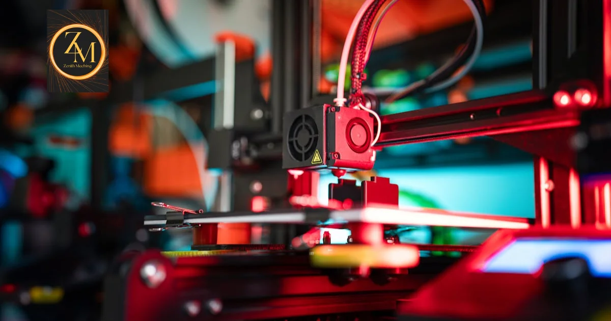
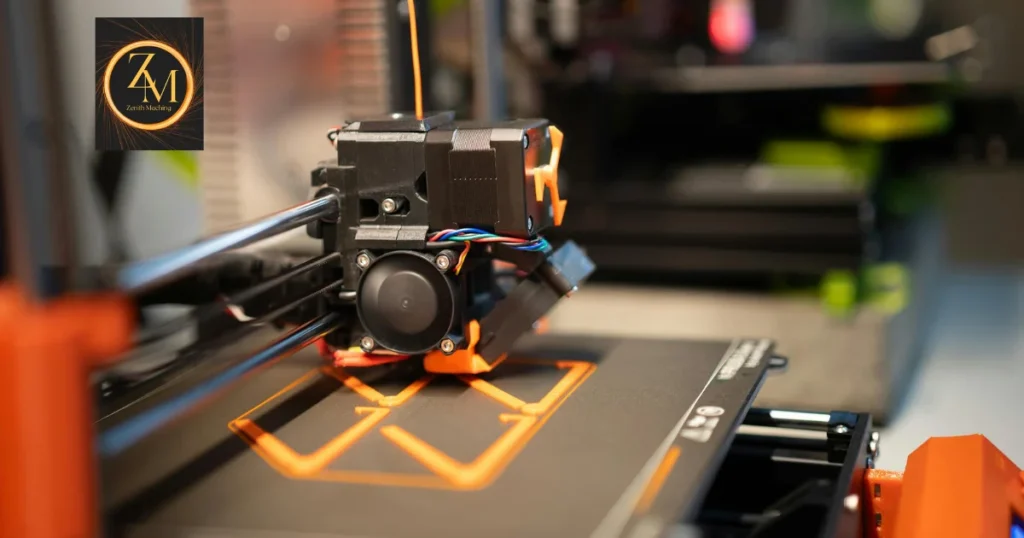
Step 3: Printing The machine executes the G-code and builds the part. Depending on the process, it either deposits molten filament, photopolymerizes liquid resin with a UV laser, or fuses polymer powder particles using a CO2 laser. Each layer bonds to the one below it before the next one starts.
Step 4: Post-Processing Most prints need work after the machine stops. FDM parts get sanded, primed, or painted. SLA parts need support removal and UV curing in a UV oven before they’re stable. SLS parts go through a breakout station to clear unfused powder, then bead blasting for surface finish. Some functional parts get machined, anodized, or dyed depending on what the application demands.
One thing that catches beginners off guard is build orientation. Parts printed vertically show weaker Z-axis strength because layer adhesion is the limiting factor, not the base material strength. Orienting critical load-bearing features horizontally is standard practice for anyone producing functional parts.
FDM, SLA, and SLS: The Three Main 3D Printing Methods

3D printing is not one technology. It’s a family of processes. FDM, SLA, and SLS are the three you’ll encounter most often in prototyping and production, and they’re different enough that picking the wrong one costs you time and money.
FDM: Fused Deposition Modeling
FDM works by melting a thermoplastic filament and extruding it through a heated nozzle onto a build plate. The deposited material cools and bonds, layer by layer, until the part is done. It’s the most accessible process and handles the widest range of materials: PLA, ABS, PETG, ASA, TPU, Nylon (PA), Polycarbonate, PEEK, and Ultem all run on FDM machines at the right temperatures and enclosure conditions.
Layer heights typically run from 0.1 mm to 0.3 mm. Surface finish is the roughest of the three main processes. Visible layer lines are standard without post-processing. FDM is the right call for functional prototypes, jigs, fixtures, and concept models where speed and cost matter more than surface quality.
SLA: Stereolithography
SLA uses a UV laser to cure liquid photopolymer resin layer by layer. The build platform lowers into a resin vat, the laser traces each cross-section on the surface, and the cured layer moves down to expose fresh resin for the next pass. SLA produces parts with surface roughness values as low as Ra 0.2 µm before any post-processing. That’s the finest surface finish you’ll get from a standard 3D printing process.
Engineering resin options include ABS-like, PC-like, flexible, castable, dental-grade, and medical-grade variants. The tradeoff is real, though. SLA parts are brittle if under-cured, and standard resins degrade under prolonged UV exposure. Post-curing in a UV oven after printing is non-negotiable if you want mechanically stable parts.
SLS: Selective Laser Sintering
SLS uses a high-powered CO2 laser to sinter polymer powder particles inside a heated powder bed. PA12 is the most widely used material, followed by PA11 and TPU powder for flexible parts. Because the surrounding unfused powder supports the build throughout the process, SLS requires no support structures at all. That’s what makes it the right tool for complex geometries, thin walls, and interlocking assemblies that would need supports in FDM or SLA.
Parts from SLS typically reach 93 to 97% density under standard conditions. Bead blasting after the breakout station improves surface finish. If you need functional part performance and geometric freedom, SLS delivers both. Surface aesthetics straight off the machine aren’t its strength, and post-processing addresses that.
Process Comparison Table
| Property | FDM | SLA | SLS |
|---|---|---|---|
| Material | Thermoplastic filament | Photopolymer resin | Nylon / TPU powder |
| Layer Height | 0.1 to 0.3 mm | 0.025 to 0.1 mm | 0.08 to 0.15 mm |
| Surface Finish | Rough (Ra 10 to 20 µm) | Smooth (Ra 0.2 to 1.5 µm) | Moderate (Ra 5 to 15 µm) |
| Supports Required | Yes | Yes | No |
| Typical Accuracy | ±0.2 to 0.5 mm | ±0.025 to 0.1 mm | ±0.2 to 0.3 mm |
| Best For | Prototyping, fixtures | Detailed models, dental, jewelry | Functional parts, complex geometry |
| Part Density | N/A | ~100% (cured resin) | 93 to 97% |
Additive Manufacturing vs Traditional Manufacturing
The real question isn’t whether 3D printing is better than CNC machining or injection molding. It’s which process fits the job. They serve different stages and different volume requirements.
CNC machining starts with a solid block and removes material until the part is done. It holds tighter tolerances: ±0.025 mm on standard setups, and ±0.005 mm or better on precision work. Metal structural parts with load-bearing requirements usually belong on a CNC machine, not a 3D printer. The tradeoff is that CNC struggles with internal geometry. Internal channels, lattice structures, and organic surfaces require specialty fixturing or become impractical entirely.
Injection molding produces parts at low per-unit costs once you’re running volume, but mold tooling runs from $5,000 on the low end to over $100,000 for complex multi-cavity tools. 3D printing has zero tooling cost. At volumes under roughly 500 to 1,000 parts (depending on part size, material, and geometry), 3D printing costs less per unit. Past that threshold, injection molding wins on economics.
Here’s how that plays out in practice. A product engineer designing an enclosure for a medical device prototype starts with SLA. The surface detail is tight, turnaround is fast, and there’s no tooling to buy or scrap when the design changes after fitment review. If the design stabilizes and production volume hits 10,000 units annually, the same engineer moves to injection molding. 3D printing and injection molding aren’t competitors. They serve different stages of the same product lifecycle.
Where 3D Printing Gets Used Across Industries

3D printing has moved well past desktop hobbyist use. Industrial applications are running across aerospace, medical, automotive, dental, and custom tooling today.
In aerospace, GE Aviation produces fuel nozzle components in Inconel 625 using Selective Laser Melting. Parts that previously required brazing and assembly of multiple components now print as a single piece. In medical, patient-specific implants and surgical guides print in Ti-6Al-4V or medical-grade PA12, with ISO 13485 and FDA 21 CFR Part 820 compliance governing every step of the process.
Automotive engineers use FDM to produce prototype brackets, clips, and interior trim pieces for fitment validation before anyone commits to production tooling. Dental labs run desktop SLA machines with dental-grade resins to produce crowns, surgical guides, and clear aligner molds. Custom orthotics and prosthetics in TPU come off SLS machines where fit, flexibility, and patient-specific geometry all have to work together.
On the shop floor, jigs and fixtures that used to get machined are increasingly FDM-printed in Nylon or Polycarbonate. The parts have short service lives and don’t need tight tolerances. Printing them cuts lead time from days to hours and keeps the CNC machines free for revenue-generating work.
Choosing the Right Process as a Beginner
3D printing gives engineers a fast, low-cost path to physical parts without tooling. But the process choice matters more than most beginners expect. FDM is fast and cheap, and the surface finish shows it. SLA is precise with excellent detail, and the material limitations are real. SLS handles functional complexity without supports, and it’s the process serious production work moves toward.
Get your part requirements defined before you pick a process. Nail down your tolerance needs, required material properties, surface finish expectations, and production volume. Those four factors point you to the right method faster than any comparison chart. If your part needs metal properties or sub-0.025 mm tolerances, 3D printing is the prototyping tool and CNC machining or casting is the production answer. Knowing where each technology fits is the difference between a smooth development cycle and an expensive lesson in process selection.
FAQ
What is 3D printing used for in manufacturing?
3D printing is used for prototyping, custom parts, tooling aids, medical devices, and low-volume production runs where traditional tooling costs are too high. SLS and SLM are also used for end-use functional parts in aerospace and medical applications where complex geometry and material performance both matter.
How accurate is 3D printing compared to CNC machining?
FDM accuracy typically runs ±0.2 to 0.5 mm. SLA achieves ±0.025 to 0.1 mm. SLS runs around ±0.2 to 0.3 mm. CNC machining holds ±0.025 mm on standard setups and tighter than ±0.005 mm on precision work. For tolerance-critical parts, CNC machining is the right tool.
What materials can be 3D printed?
Common materials include PLA, ABS, PETG, Nylon (PA12, PA11), TPU, PEEK, Polycarbonate, standard and engineering photopolymer resins, and metal powders including 316L stainless steel, Ti-6Al-4V, Inconel 625, and AlSi10Mg. The available materials depend entirely on which process you’re running.
Is 3D printing cheaper than injection molding?
At low volumes, typically under 500 to 1,000 parts, 3D printing is cheaper because there’s no tooling cost. At higher volumes, injection molding’s low per-unit cost outweighs the upfront mold investment. The crossover point shifts depending on part size, material, and geometry complexity.
What is the difference between FDM and SLA?
FDM deposits melted thermoplastic filament. SLA cures liquid photopolymer resin with a UV laser. SLA produces significantly smoother surfaces and tighter dimensional accuracy. FDM works with a wider range of engineering thermoplastics and is generally faster and cheaper for larger, lower-detail parts.
What does layer height mean in 3D printing?
Layer height is the thickness of each horizontal slice deposited or cured during printing. Thinner layers at 0.05 mm produce smoother surfaces but increase print time. Thicker layers at 0.3 mm print faster but show visible layer lines and reduced detail resolution. Most functional FDM parts run at 0.15 to 0.2 mm as a practical balance.